Solar That Fits the Airport — Not the Other Way Around.
Vertical bifacial solar deployed along perimeter fencing and access roads — engineered for FAA glare compliance, high-wind survivability, and zero additional land use.
Airports Want Solar. Traditional Solar Doesn't Want Airports.
Glare Risk
Traditional tilted panels create upward reflection vectors that can disrupt pilots and air traffic control. Real-world glare incidents have forced mitigation or removal of installations near runways — this is an operational risk, not a theoretical one.
Land Constraints
Runway safety areas, taxiway object-free zones, approach height restrictions, and security buffers already claim nearly every usable acre. Most airports simply don't have unencumbered land for a conventional solar farm.
Regulatory Exposure
FAA policy requires site-specific glare analysis and Form 7460-1 submission before construction. Skip it, and the airport bears full financial responsibility for any post-construction mitigation.
What the FAA Actually Requires
The FAA doesn't publish one universal design standard for airport solar. Compliance is based on site-specific analysis tailored to each airport's runway orientation, tower position, and approach corridors. Every project must:
- Analyze glint and glare impacts on ATC towers and final approach paths (typically within ~2 miles)
- Submit FAA Form 7460-1 confirming no visual hazard will be created
- Accept financial responsibility for any post-construction mitigation
A momentary reflection lasting seconds; an annoyance, not typically a hazard.
A sustained reflection capable of temporary visual impairment. This is the FAA's primary concern, because it can compromise a pilot's or controller's vision during critical operational phases.
Because glare risk depends on solar angle, panel tilt, approach path, and observer location, computer modeling — not guesswork — is required before construction begins.
Every Deployment Is Modeled Before It's Built
We use the Solar Glare Hazard Analysis Tool (SGHAT), commercially provided through ForgeSolar — the de facto simulation platform accepted by the FAA for airport solar permitting. It predicts exactly when and where glare could occur, based on sun position, panel geometry, and observer sightlines, before a single panel is installed.
- STEP 01
Sun Position & Panel Geometry
Model sun angles year-round for the specific site.
- STEP 02
Flight Path & Tower Mapping
Define sightlines that must stay glare-free.
- STEP 03
Hazard Classification
No impact / low after-image potential / ocular hazard, for every hour of the year.
- STEP 04
FAA Form 7460-1 Submission
Simulation results become the formal safety justification.
Changing the Angle Changes Everything
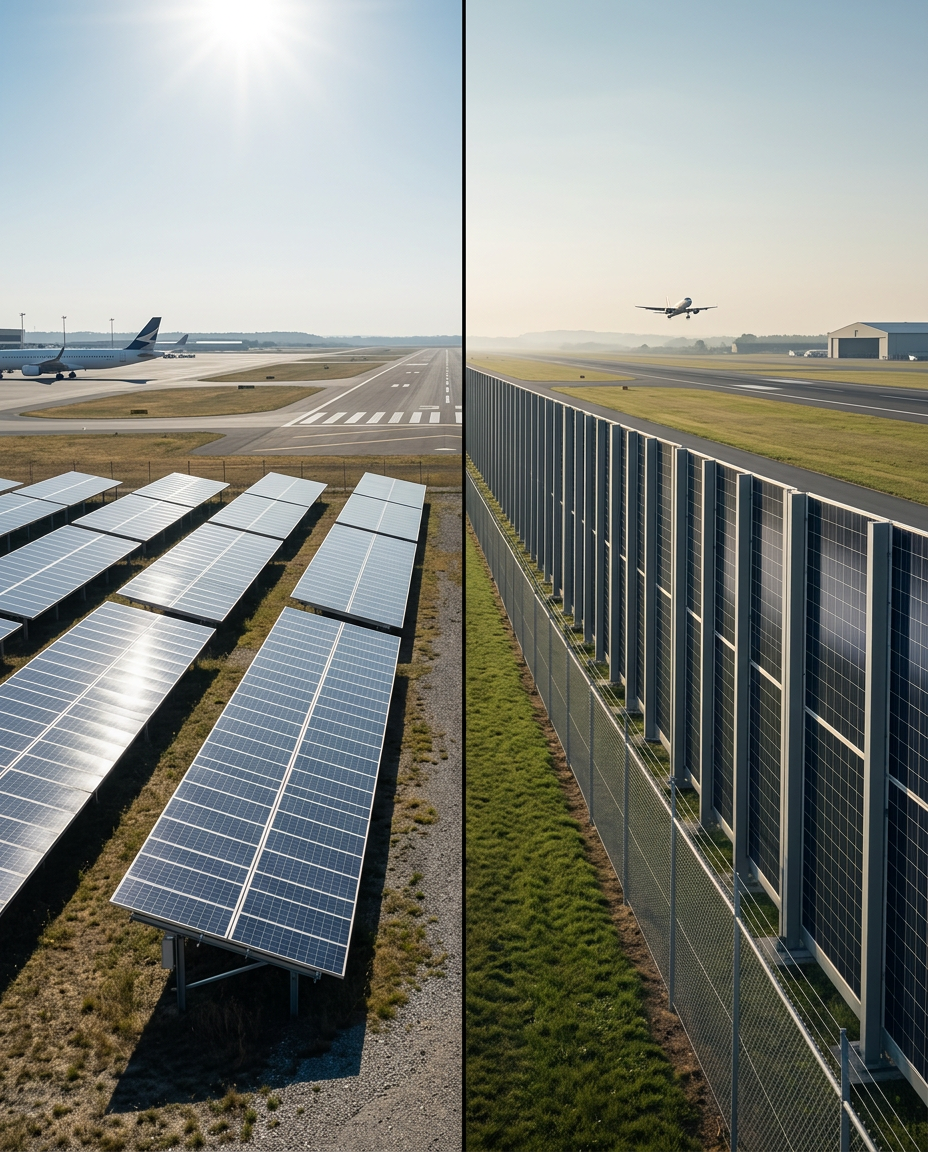
Tilted arrays are optimized for maximum direct capture — but the tilt angle that maximizes energy production is often the same angle that maximizes upward reflection risk toward aircraft on approach.
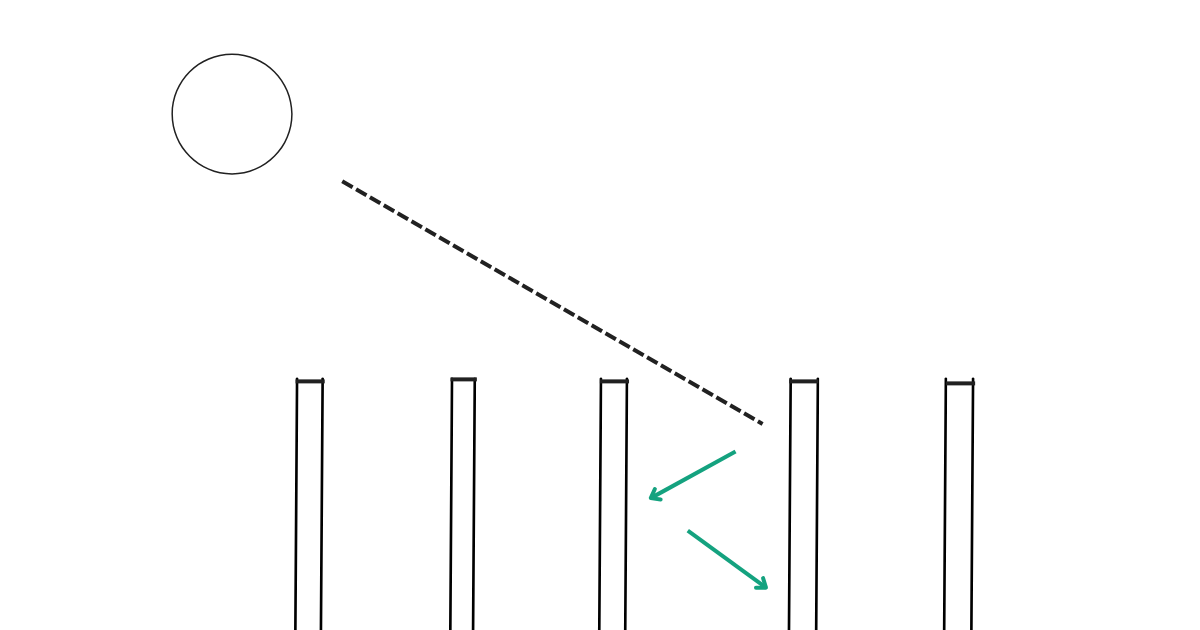
At 90°, the reflective surface faces the horizon rather than the sky. Specular reflection is directed laterally across the ground, keeping the primary glare angle outside the pilot's eye path during approach and landing.
Airports Are a Natural Fit for Vertical Solar
CFD simulations conducted by Fraunhofer ISE on vertical bifacial PV systems found no measurable lift at wind speeds up to 47 m/s (approximately 105 mph). While that testing was conducted on a different manufacturer's system, it reflects a broader pattern in vertical solar research: the fence-like, low-profile orientation behaves aerodynamically more like perimeter fencing than a tilted array, reducing uplift risk by design. Site-specific structural engineering and wind analysis is conducted for every Sunzaun installation to confirm performance for the specific location and configuration.
Fraunhofer ISE CFD results on vertical bifacial PV systems.
Site-specific structural engineering and wind analysis is conducted for every Sunzaun installation to confirm performance for the specific location and configuration.
Every Linear Foot You Already Build Becomes an Energy Asset
Runway safety areas, object-free zones, and security buffers already claim nearly every acre an airport has. Vertical solar doesn't compete for that land — it co-deploys on infrastructure airports are already required to build.
Perimeter Fencing
Could replace or augment standard security fencing already required by FAA and TSA standards. Integrated security features are being developed.
Parking Lots & Structures
Boundary lines of surface lots and garages offer extensive linear footage, often already near electrical infrastructure.
Access Roads & Buffer Zones
Low-conflict deployment pathways with proximity to terminal and support-facility power infrastructure.
Vertical Solar Output Follows the Airport Day
Airport energy use ramps up in the morning and stays high through the evening. Vertical east-west solar produces a V-shaped generation curve with more output in the morning and afternoon and less at solar noon — spreading production across the hours the airport is most active.
Schematic comparison of a typical airport demand curve and the normalized output profile of vertical east-west bifacial solar. Actual output varies by site, season, and configuration.
When oriented east-west, vertical bifacial systems produce relatively more electricity in the morning and late afternoon than conventional south-facing arrays. This production profile can better align with airport operations that remain active throughout the day, rather than concentrating generation around solar noon, and can improve the value of the electricity produced.
This isn't theoretical. It's already flying.
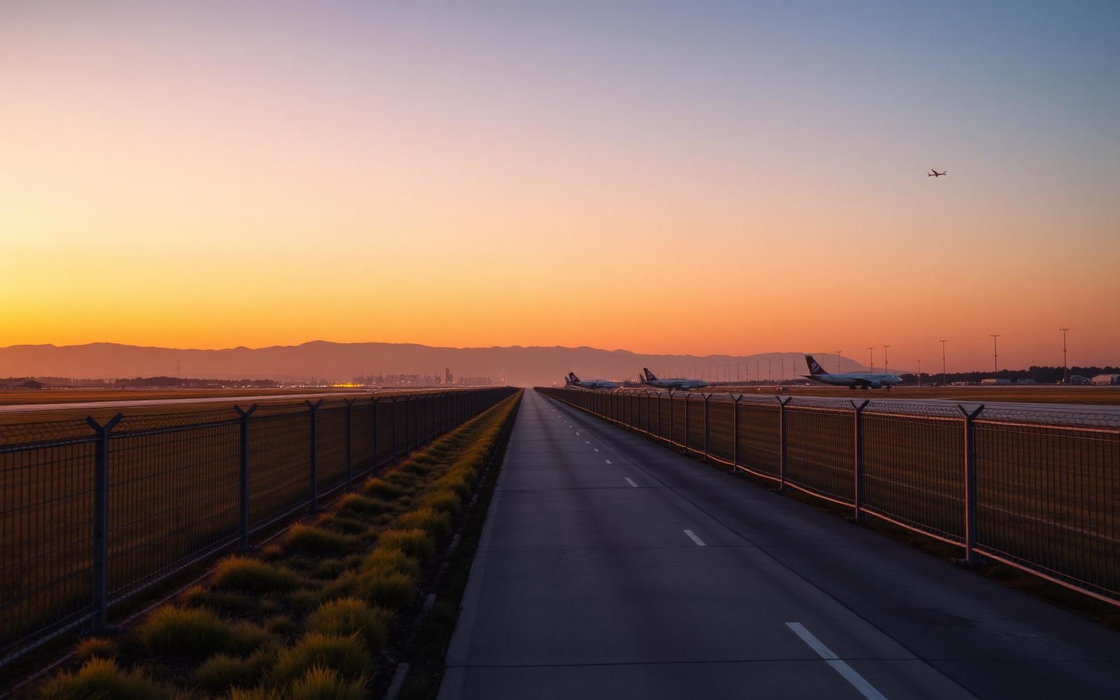
Frankfurt Airport — one of the busiest in Europe — has commissioned a 2.8-kilometer vertical bifacial solar installation along its runway, generating 17.4 MW.
Operator Fraport chose vertical orientation specifically to minimize land impact and protect the biodiversity beneath the panels, while shifting generation toward the morning and afternoon hours when the airport needs power most.
It's the largest vertical solar installation at any airport in the world — and a working demonstration that vertical solar can operate safely within an active airfield environment.
- 2.8 km
- Perimeter length
- 17.4 MW
- Installed capacity
- #1
- Largest airport vertical solar installation worldwide
From Site Assessment to Installed System
- 01
Site Layout Review
We collaborate with project engineers to identify viable deployment zones along perimeter fencing and access roads.
- 02
Glare Analysis Support
We support the project team throughout the glare analysis and FAA Form 7460-1 submission process.
- 03
Structural Engineering
We provide a stamped and sealed structural drawing from a licensed geotechnical engineer.
- 04
Racking & Installation
We supply the racking system and provide professional installation services for the project.
Every airport has a different runway orientation, tower position, and approach path. We work with the project team on a site-specific assessment, not a standard layout, to help ensure the system fits both the airfield and the site conditions.
Find Out What Your Perimeter Can Do
We're happy to collaborate with project engineers to identify viable deployment zones and support the project team throughout the glare analysis and FAA Form 7460-1 submission process.